
This article covers the two different types of relays and how to correctly land the wires.
Prominent 51X and Edge 500 Series Controllers have three main ways to connect additional feed equipment for control powered contacts, dry contacts, and digital output. This article will focus on the two types of contacts.
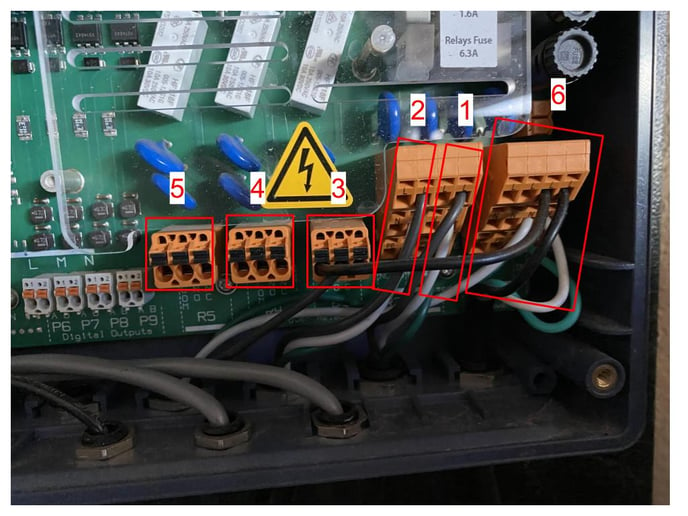
Diagram:
1 - Relay 1
2 - Relay 2
3 - Relay 3*
4 - Relay 4
5 - Relay 5
6 - Power Distribution
Power Distribution
Main power coming into the controller is landed on the power distribution block. Devices needing power can have wires landed on the power distribution block. To insert or remove wire from Power Distribution Block insert small flathead screwdriver in tab above wire slot to allow for wire to be inserted or removed. Remove screwdriver to restore tension on wire.
Input Labels
Labels can be seen underneath the contact blocks indicating what each input does on the controller. Below is what each label stands for.:
L- Line Power
N - Neutral
PE - Ground
COM - Common wire landed here is connected to the NO and NC side of the relay depending on the state of the relay (On/Off)
Relay I/O labels
NO: Normally Open ( relay contact is open if powered off, the controlled device would not receive power if off)
NC: Normally Closed (relay contact is closed if powered off, the controlled device would receive power if off)
If you are unsure which to use consult an expert or use NO as most cases call for this type of relay use. The NC side of the relay is used very infrequently.
Relay 1 and 2
Relay 1 and 2 are powered relays with 120v. Powering devices off these relays require no further configuration. These can not be configured as a dry contact.
Relay 3 - 5
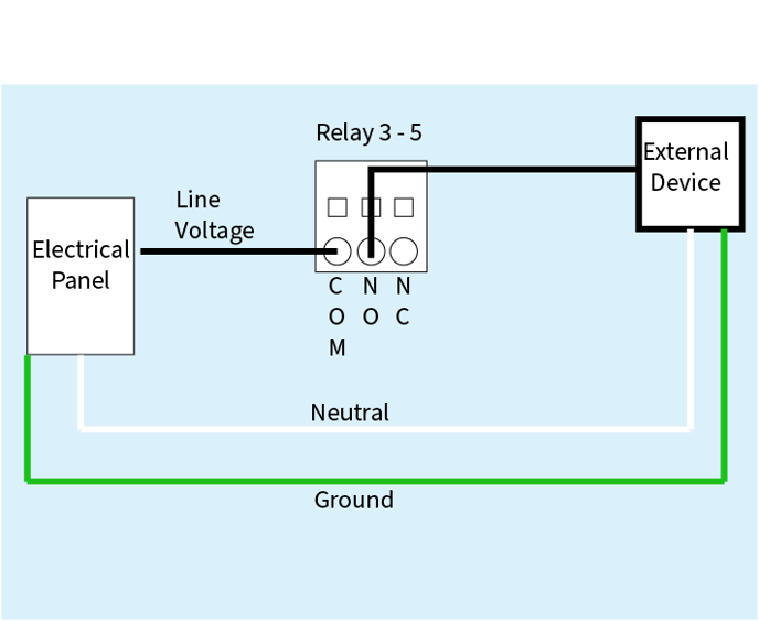
These relays are “dry contacts” meaning they do not already have power. These are used to switch on and off devices that do not need power from the controller. If the device simply needs an On/Off signal supplied land the two wires designated by the feed devices manual. Additionally if needed these relays can be used to interrupt power to remotely power on or off a device that is not getting its power from the controller.
To interrupt power:
Land the Line voltage wire on the COM input. Land the wire that when connected to line voltage provides power to the device on the NO input.
Basic Schematic:
However if a device needs powered by the controller follow directions below.
How to Power an external device with Relay 3-5
- Ensure controller is powered off
- Connect a small jumper wire from “L” on the power distribution block to “COM” on whichever relay is being used.
- Land power wire from external device on “NO” on whichever relay is being used.
- Land Ground wire on PE in power distribution block
- Land Neutral wire on N in power distribution block
*Your relay should look like relay 3 in the first photo above if steps completed correctly
FAQ
Why is my feed device turning on when the relay turns off ?
Check that the wires for this specific relay are not landed on the Normally Closed side of the relay. This would cause the feed device to be on when the relay is off and vice versa.
Why is my feed device constantly on?
Check that the feed device isn't wired to constant power on the power distribution block. If it is it will need to be landed on the correct relay. If this isn't the relay may have failed causing the relay to have constant power regardless of the state of the relay.